

 A bold claim maybe but a big puzzle nonetheless. My engineering volunteer team Andy and Gill found these rusting cast iron leviathans stored outside whilst auditing, apparently in no particular order but next to other bits of machinery including a press, a rolling mill and a couple of large boilers. The first image appeared to be a lineshaft with a set of pulleys and two flywheels, not a common arrangement. The second picture shows, hidden in the undergrowth, a large cast iron disc with rubber inserted around the rim and a central square sockle hole. The third picture seemed to be two curved arms with bearing rests at one end. After Gill and Andy brought the audit sheets back and i was trying to reconcile what we found with accessioned items I had several trips down to try and figure out the puzzling bits and pieces and see if i could work out what they were part of. they certainly didnt seem to be part of the same thing.
I decided to have a closer look at the press because we had identified it as a blanking press made by Greenwood & Batley of Leeds. It was used at the Royal Mint in Haverfordwest but I still couldnt work out how all the bits could be part of it.
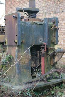 I couldnt see any power source for this press, it had no motor or pulleys for belt drive, and the other thing that struck me was the sockle on the top of the screw thread, which was square. taking measurements showed that it fitted the hole in the centre of the disc with the rubber inserts perfectly. this still seemed odd though, a horizontal flywheel? and what was the rubber for? I measured the outer diameter of the disk and then took a closer look at the gap between the two flywheels on the lineshaft - again, it fitted perfectly. and then a metaphorical lightbulb lit up and i realised how the press worked and how the pieces fitted together. The two curved arms fitted on the flat rectangular sections at the top of the press, they supported the lineshaft with the two vertical flywheels whilst the other flywheel fitted horizontally between them on the top of the screw, creating what is known as a friction drive. The leather inserts would give enough adhesion to allow the disk and the screw to be driven downwards to press out the coins or blanks but once slipped out of gear it could be skidded back into its original by the lever mounted near the sockle. Using a friction drive meant that the press screw could move in two directions without having to invest in a complex gearing system or reversing the power source, and it turned out to be a very common and still used drive for screw presses.
As an added bonus I looked up Greenwood & Batley screw press on Google and found this, the very same press in action at the Royal Mint!


Good to see something made at the Factory where I worked in the 70s (the year of the drought). As a stock control clerk I sat in a garden shed in the middle of the factory checking off, on record cards, whether we had enough screws, nuts, washers etc for the next machine being made. How much more efficient we would have been with computers but there were always holiday jobs for students back then.
ReplyDeleteB
Will this be restored?
ReplyDeleteIn response to Regular Rod, "Will it be restored?" Only if there are good reasons to invest further resources in the object, beyond the basics such as getting it indoors, recoreded and labelled, and if the funding can be secured. Funding for more than the basics is uncertain at the best of times, and allocation of precious resources is made on the basis of merit.
ReplyDelete